Echo Blind Openers - Part 1
Our first custom project was to automate the opening and closing of our living room blinds. Yes, it’s not that hard to get up and rotate the little rod on each window for 8 seconds, but it’s waaaaay cooler to just tell Alexa to do it for you (check out a previous post for an introduction to Alexa).
The idea for the project came from a visiting friend, so as a first step, we looked online for who’s done it before. Lo and behold, it’s definitely been done before (like most things). The starting point for our project was the Mini Blind Minder.
Unlike the Mini Blind Minder, we wanted to interact with our blind openers via voice command through the Amazon Echo, so our design is somewhat modified. In this post, I’ll discuss the hardware/Arduino portion of the project, and we’ll have a celebrity guest post from TheConnMan next time to discuss the interface with Alexa.
To start, here’s the list of parts we used aside from what’s already in our toolbox:
List of Parts
| Hardware | ||
|---|---|---|
|
ESP8266 Serial Wifi Wireless Transceiver Module |
 |
This little module will show up frequently in our projects. You can find it online for less than $5 and it's basically a little piece of magic that hooks up anything you want to the internet. We'll use it here to communicate with Alexa. |
|
Continuous Rotation Servo |
 |
We automated two windows, so we used two of these. You'll need as many motors as the number of windows you plan to automate. |
|
On/Off Switches |
 |
We'll need an on/off switch to reset the circuit in case something goes wonky. |
|
9V 1A Power Adapter |
 |
We'll use a power adapter like this one to permanently power the project once it's finished. When buying power supplies for the Arduino, make sure to take these guidelines into consideration. Otherwise, you may accidentally fry the Arduino. |
All right, now that we’ve got everything, we’ll first want to build a prototype of our design to make sure everything works. The easiest way to prototype for the Arduino is using a breadboard. The breadboard makes it easy to switch things up without having to take everything apart. We’ll test each module by itself and then put things together once we’re sure each component works individually.
Run and calibrate the motors
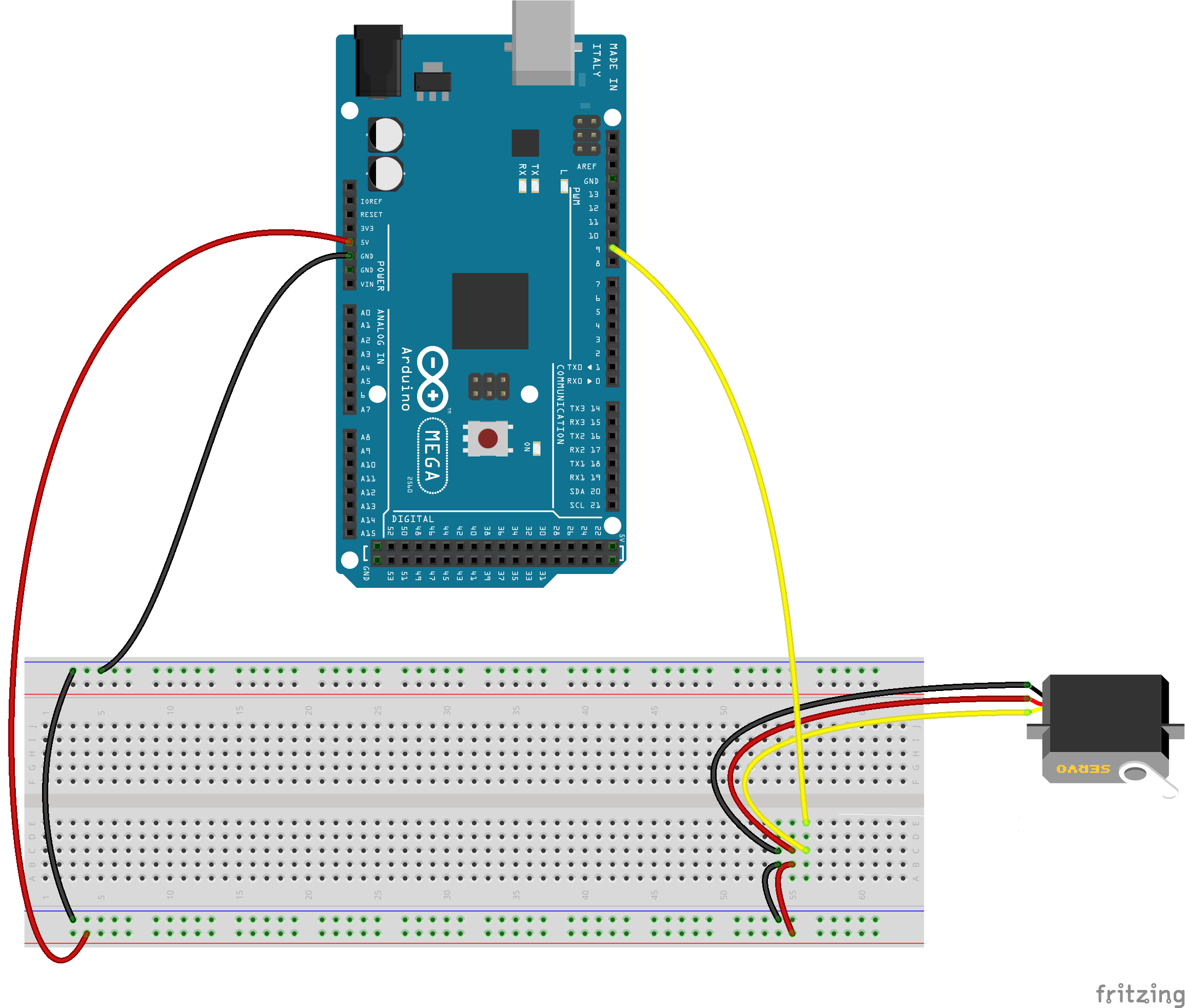
To test out the motors, plug them into your breadboard and connect to the Arduino as shown below. On our motors, the red wire is power, black is ground, and white (on our diagrams I’ll show them as yellow) is the switch that tells the motors to turn on and off. Note that our servos will need 5V to run. Make sure to test one servo motor at a time to make sure each works as intended.
The Mini Blind Minder project conveniently has a pre-made script to calibrate your motors. Click through to step “6. Calibrate the servo.” in the project to download the .zip file with the Arduino sketches and run them on each motor.
Blog building side-note: there’s a super cool, open-source package called fritzing that allows you to create fancy-looking schematics and diagrams–that’s what I’m using here to show you >our setups.
Modify the ESP8266
Next, we’ll want to test out the ESP8266. Unfortunately, the way it’s built out of the box isn’t compatible with a breadboard since some pins will always end up on the same lines. Since the modules are so cheap, we bought a few and designated one as the prototype chip. We used these instructions to make it breadboard friendly. Now we can plug in half of the pins on one side of the breadboard, and the other four pins on the other side.
Run the ESP8266
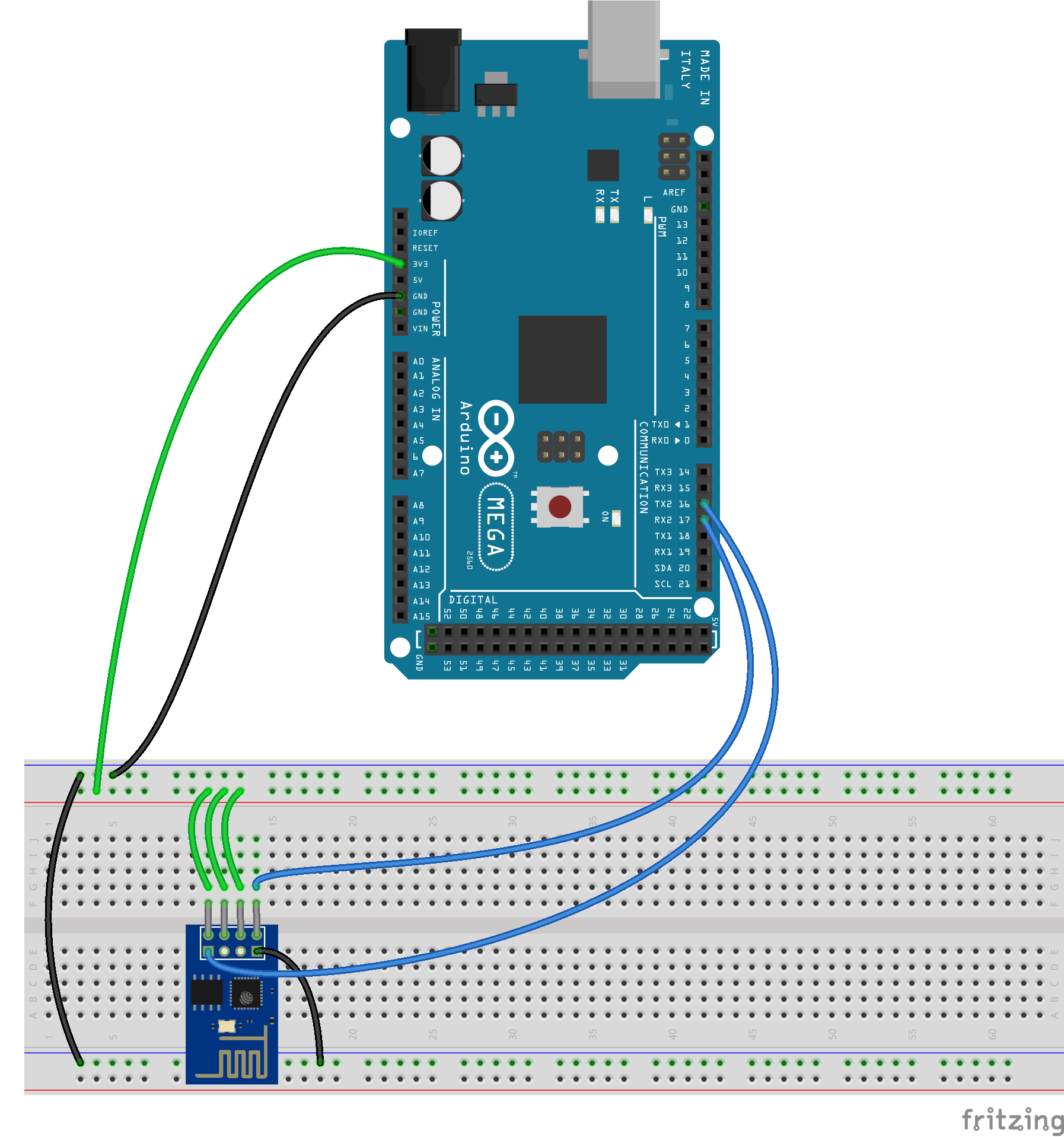
Now we’ll need to learn a little bit about the ESP8266. This post titled noob’s guide to ESP8266 with Arduino Mega 2560 or Uno is very comprehensive and even provides some example scripts to run to make sure your chip is functioning properly. Here’s how we hooked up our modified chip: the green wires are power, black is ground, and blue are the communication wires (you won’t have the gray wires once you’ve modified the chip–it’ll just plug in to the other side of the board). IMPORTANT NOTE: The ESP8266 chip requires 3.3V of power, NOT 5V, so we’ll need to make sure to make that distinction when we put both the motors and the chip together.
Build the prototype
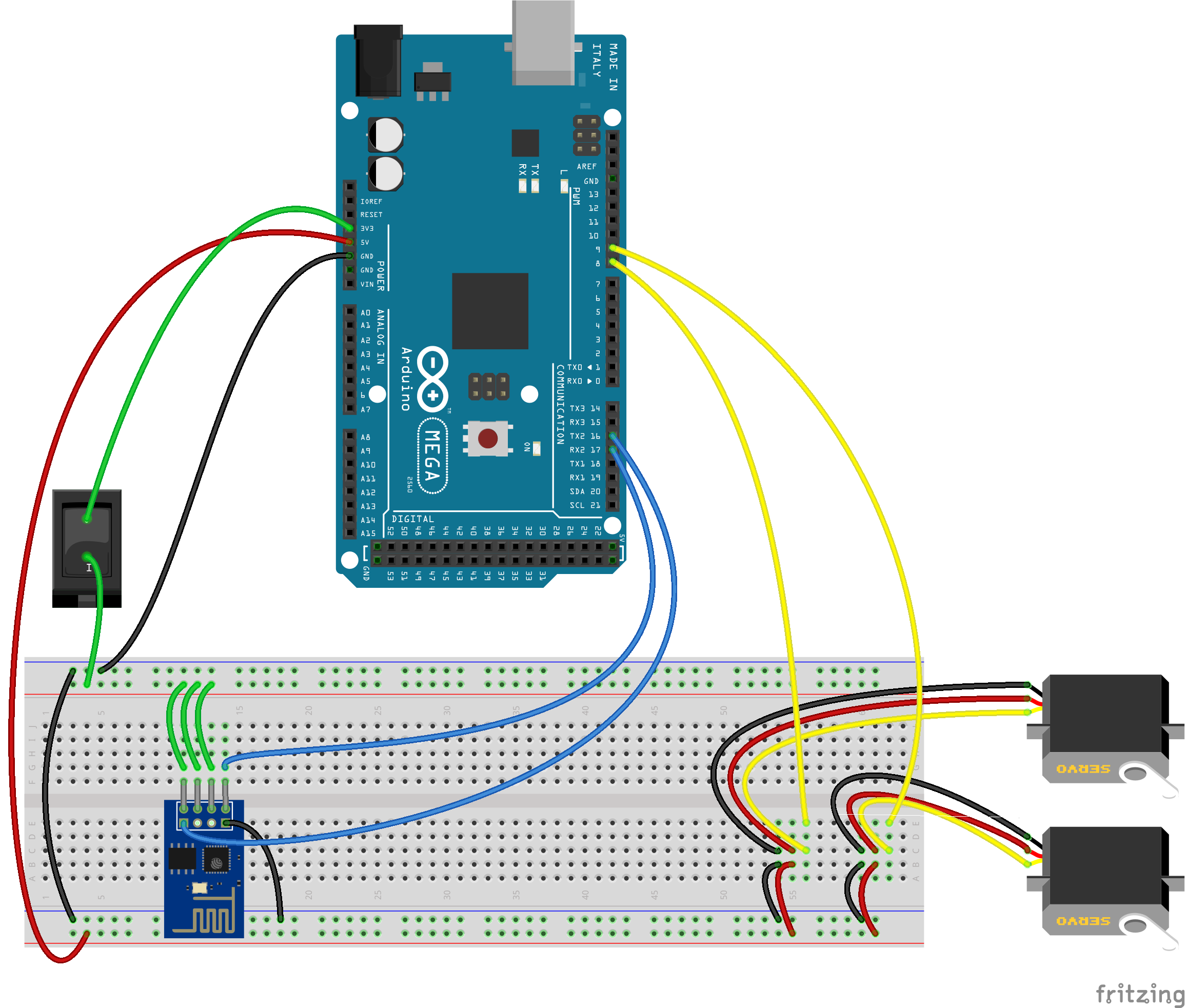
All right! Now that each component is working properly, let’s put it together! Note the following:
- The top part of the breadboard in the diagram is at 3.3V
- The bottom part of the breadboard is at 5V
- The grounds are all connected
- There is a switch on the 3.3V power so that we can turn it on and off at will
- There are two servo motors, one hooked up to pin 8 and the other to pin 9
Here is a schematic without the breadboard to show how everything is connected. I used the Arduino Uno for this diagram only because it’s slightly smaller. The Mega has all of the same pins, plus more, so it doesn’t matter for the schematic.
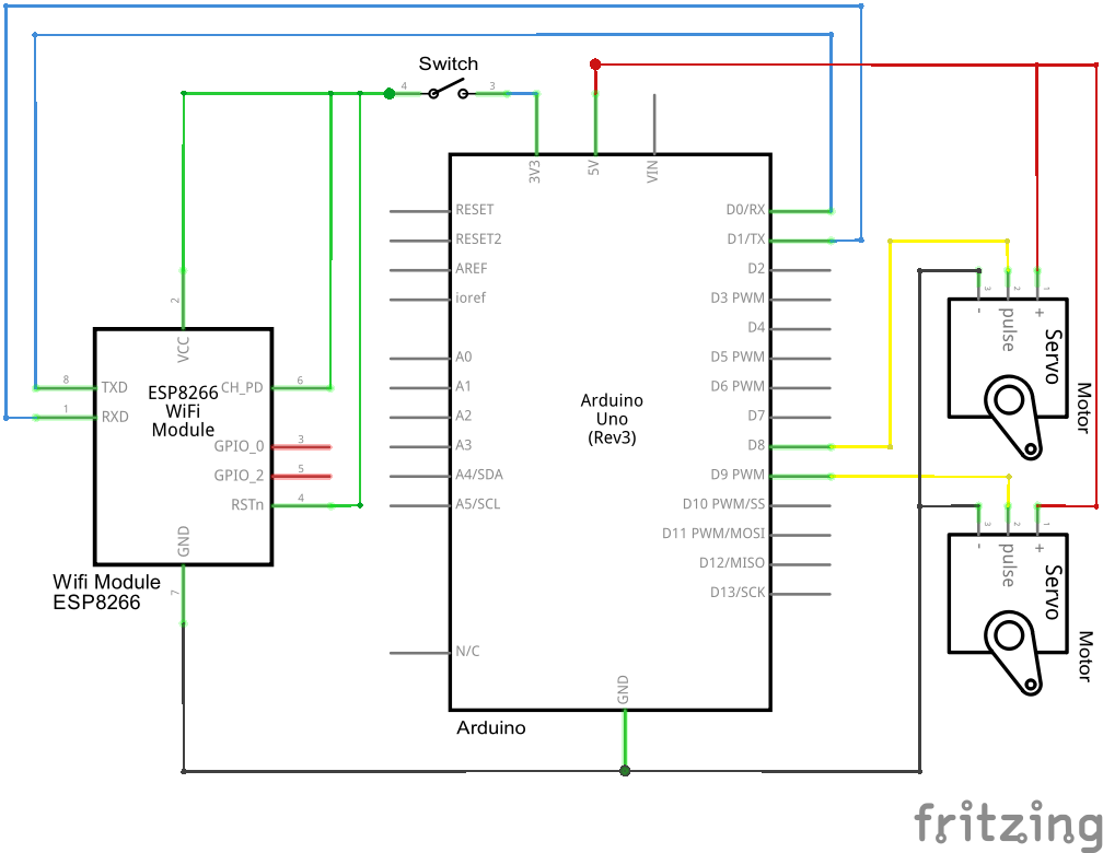
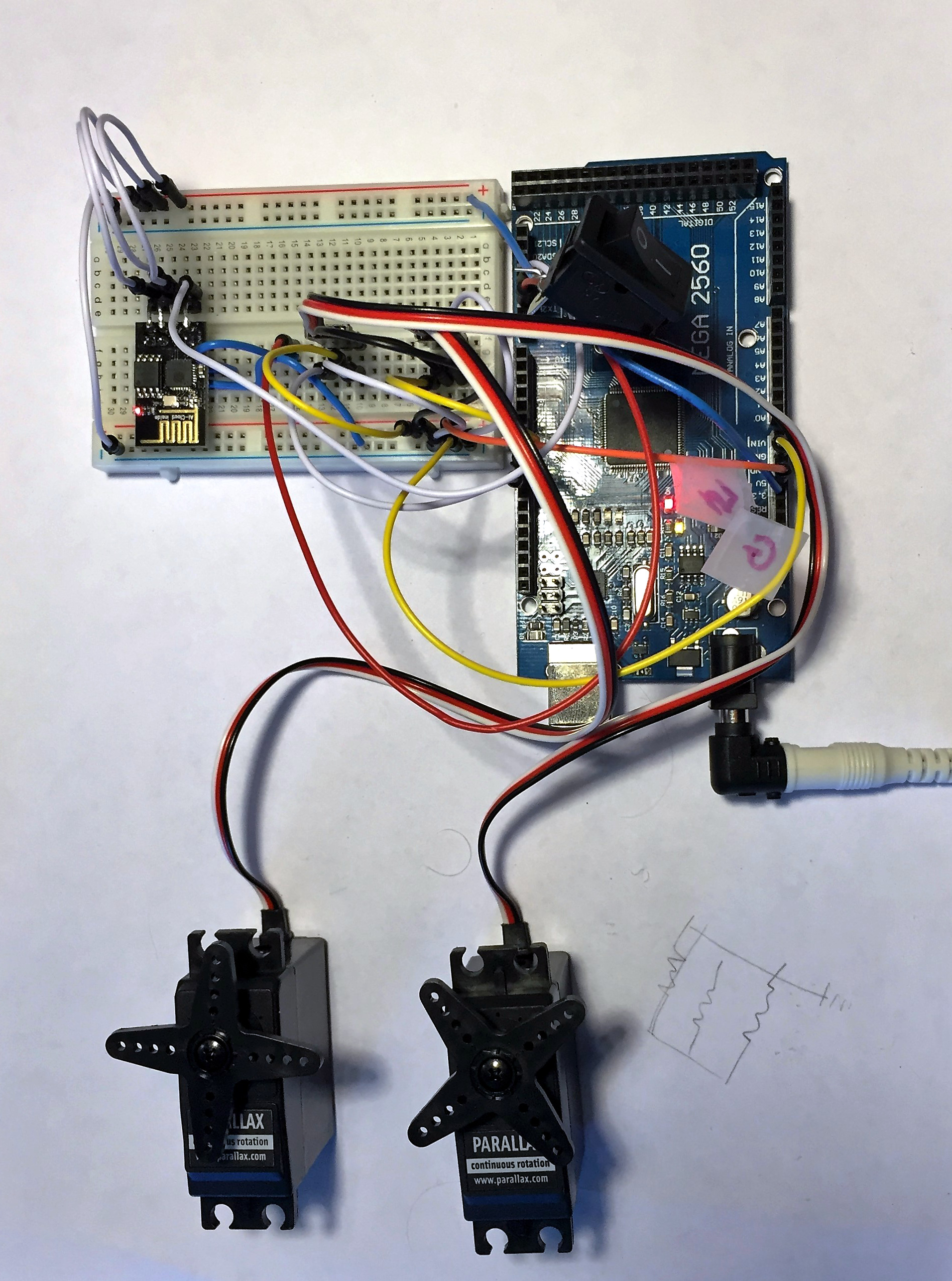
And here is a picture of our actual setup. Don’t pay attention to the colors of the wires. They don’t correspond to the diagrams.
Run the code
Finally, we’ll need to run the Arduino code to bring the project to life. We’re storing all of our code on Github, so if there are any updates since this post, you can find the latest here.
Some common problems you may run into when running the code, and solutions:
- Including the ArduinoJson.h and Servo.h libraries
- They’re already “included” in the code, but you’ll need to add them to the Arduino IDE. To do that, click “Sketch” at the top of the IDE, then “Include Library”. You’ll see the Servo library there, so go ahead and select it. To find the ArduinoJson library, select “Manage Libraries…” and search for it there.
- Creating a config.h file
- You’ll need to create your own config file and store it in the same folder as your echoblinds.ino sketch. It will contain sensitive information like your network password, so make sure not to share it with everyone. We keep ours in the .gitignore part of our repository. The config.h.example file shows you how it should be structured and what info you’ll need to include (yes, include the quotation marks).
- To see the printed lines, once you run your sketch, click on “Tools” and then “Serial Monitor” or Ctrl+Shift+M. If anything doesn’t work, my approach is usually to add a bunch of Serial.println lines throughout the code to see where things break.
For convenience, here’s the sketch as well:
Next week on Pretty Dece, TheConnMan will show us how to start talking to Alexa!
Happy automating!!
- JMad